
Having a solid understanding of how electrical power is generated and distributed will help you understand how it all works, especially when you need it most.
The first thing to do when learning the A320’s electrical system is to think of it as two distinct systems.
There is an AC system and a DC system.
The DC system is on the top and the AC system is on the bottom.
You can see what I mean in this diagram.
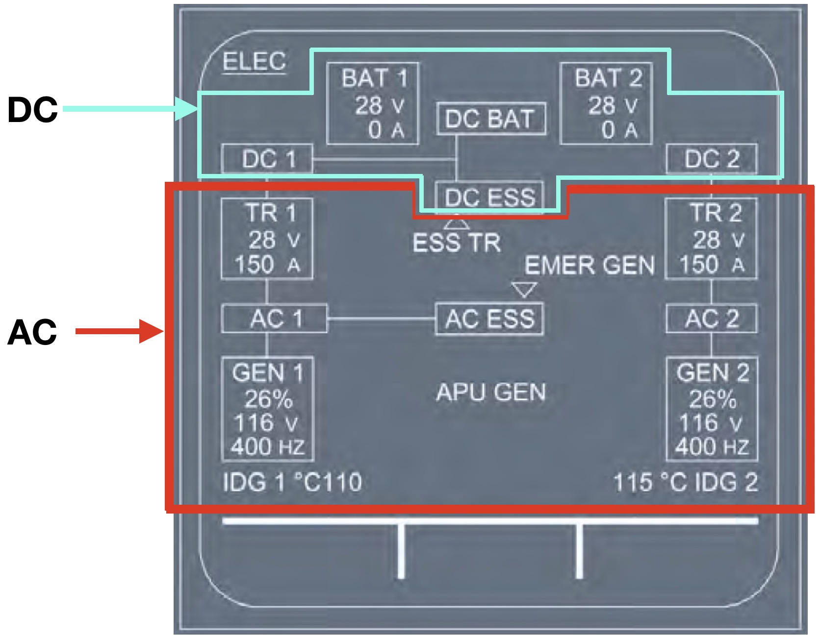
AC power is normally produced through the two ENG generators (GEN 1, GEN2), and the APU generator.
The APU generator (APU GEN), although not driven by either engine, is an identical piece of equipment and capable of producing the same output, as the engine-driven gens.
It’s important to understand a few basic concepts:
First of all, the three main generators (GEN 1, GEN 2 or the APU GEN) produce AC power.
Any one of these three generators (GEN 1, GEN 2 or the APU GEN) can then supply that AC power to all electrical busbars.
This is great for all of the systems that use AC power but not so good for the others that require DC power.
So, to supply these DC users, the system takes a portion of the AC power and transforms it into DC power.
This conversion is done by the TR units, hence the name, transformer-rectifier.
But what happens if normal AC power from the three GENS is not available?
In other words, what happens if GEN 1, GEN 2 and the APU GEN are all inop?
In this case, an EMER GEN can provide AC power at a reduced level.
Much like the normal system, the EMER GEN takes a portion of this AC power and converts it into DC power for certain users through a dedicated TR unit.
In the rare event that even the EMER GEN is not functioning there will be NO AC POWER available.
As many of the aircraft’s most important systems require AC power, this is quite obviously, not a very good thing.
So, as a last resort, the electrical system can take DC power from the batteries and invert it into AC power, and this is the sole function of the STATIC INVERTER.
However, since the batteries are not really meant for this, there’s not much power produced and many aircraft systems will be unpowered should this occur.
Airbus estimates that the batteries will last for 20-30 minutes.
They don’t specify what happens after that, but you can probably do the math!
I mentioned earlier that the entire system normally needs AC power to function.
Luckily, the A320 is equipped with a few different sources of AC power.
Let’s take a look.
Ready for your next Checkride?
Probably not as ready as you should be.
Certainly not as ready as you could be.
Click here to find out more about the world’s first and finest, complete emergency management system designed especially for the A320.
There are two engine-driven generators (GEN 1/GEN 2).
Each one is driven by its respective engine through an integrated drive.
I’m sure some of you will encounter Checkers who want to know the power output of the generators.
With that in mind, each generator can supply up to 90 KVA of power at 115 and 200 volts and 400 HZ.
The engine-driven generators are controlled by a GCU or Generator Control Unit.
Each Generator Control Unit can:
- Control the frequency and voltage of the generator output, and,
- Protect the network by controlling the respective generator line contactor.
- This means that the GCU can open or close the generator line contactor to connect or disconnect the generator from the rest of the system.
The APU drives its own generator and this mofo can produce the same power as either of the engine-driven generators.
In addition, it can replace either or both ENG GENs at any time, as long as the aircraft and environmental limitations are respected.
Much like the engine-driven generators, the APU has a control unit.
It’s called the GAPCU, which stands for GROUND and AUXILIARY POWER CONTROL UNIT.
It functions similarly to the GCU and,
- Controls the APU’s output, and
- Protects the network by controlling the APU generator’s line contactor.
When you’re on the ground, a hookup near the nose wheel allows AC external power to be supplied to all busbars.
The GAPCU controls the External Power Line Contactor.
- Controls startup of the EMER GEN.
- Keeps the EMR GEN running at a constant speed.
- Controls the EMER GEN’s output voltage.
- Protects the network by controlling the EMERGENCY GEN line contactor.
The static inverter is an interesting and crucial piece of equipment on the A320.
It takes DC power from BAT 1 and inverts into AC power (1 KVA).
It’s not a lot of power, only 1 KVA, but if that’s all you’ve got, trust me, you’ll be happy to have it!
Anyway, this tiny bit of juice is then supplied to the AC ESS BUS.
This will happen if all AC power sources have been lost.
This means a loss of GEN 1, GEN 2, the APU GEN and the EMER GEN.
In this case, the batteries become the only source of electrical power.
Remember when I said that Airbus estimates that the batteries will last for 20-30 minutes.
Better start the clock!
DC power on the A320 can be generated in two ways, either from the TR units or the Batteries.
Let’s take a look.
- DC BUS 1
- DC BAT BUS
- DC ESS BUS
TR2 is normally supplied from AC BUS 2 and sends DC power to DC BUS 2.
There is also a third TR called the ESS TR, which converts AC power from the Emergency Generator into DC power.
It is only used when:
- All ENG GENs and the APU have failed to supply power to the network
- TR 1 fails
- TR 2 fails
The ESS TR supplies this power to the DC ESS BUS.
The contactor of each TR will open automatically for:
- Overheat
- Min current
There are two types of CBs: Monitored and Unmonitored.
Monitored CB’s are coloured Green and when popped for more than 1 min, a CB TRIPPED ECAM will be generated telling you the location of the affected CB.
Non-monitored CB’s are coloured BLACK.
WTB (Wing Tip Brake) CBs are capped in red to prevent them from being reset.
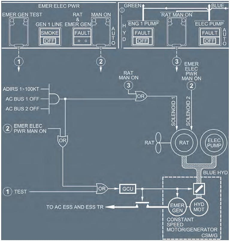
The Generation of Emergency power in the Airbus A320
- When the aircraft’s speed is above 100 knots and normal AC power becomes unavailable, the RAT will drop out from the left side of the aircraft’s belly fairing.
- The RAT (RAM AIR TURBINE) is a small propeller.
- When the RAT starts spinning, it powers the BLUE HYD system, which then drives a hydraulic motor, which powers the EMER GEN.
So that’s been our look into the basic structure of the A320’s electrical system.
As always, I hope you found it informative and maybe even a bit enjoyable.
By now, you should have a slightly better idea of the importance of how the AC and DC systems are organised and how they work together.
I wish that were all there was to the thing, but there’s a bit more.
See, while we also touched on the very basics of emergency power, you’ll find many more ponderables in our lesson dedicated to the Emergency Electrical Configuration in the A320.
Be kind, be smart, fly well.
Until next time…

First Paragraph;
The 28V DC system is on the bottom and the AC system is on the bottom.
Guess its meant to say top and bottom.
Do you have any more blog posts planned?
There is also a problem resetting passwords, the reset email never arrives.
Love the content. Great Job.
G’day aaaaa!
Thanks so much for taking the time to let me know about my typo!
Sometimes with all of the writing, it can become hard to see mistakes!
I’ve just now made the correction!
Thanks also for letting me know about the password reset inop…I’ll get on it straight away!
We just released two new Slat/Flap system lessons last week and are planning to release a new Alpha Floor lesson this week.
In addition, we got some lessons about interpreting the STATUS page coming out shortly!
Thanks so much for your support…lots more coming!
Cheers Mate!
“WTB (Wing Tip Brake) CBs are capped in red to prevent them from being reset.”
Well… technically, the RED is to identify them as not to be reset. Nothing actually prevents them being reset… I mean just to be word perfectly correct!